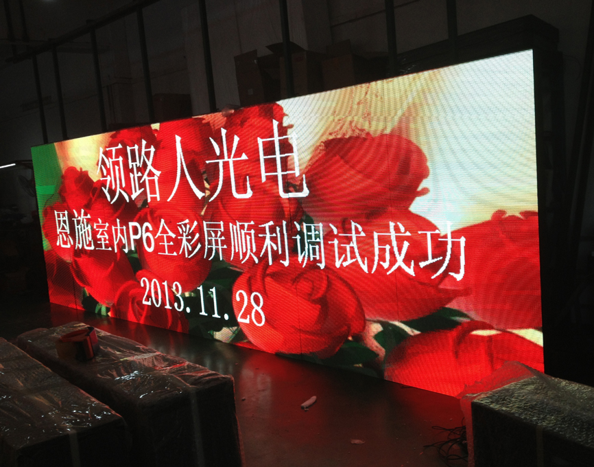
With the advent of the media age, full-color LED displays have become a medium for consumers to obtain information. Most of everyone’s impression of full-color LED displays rests on the appearance. Today, I will take you to learn more about full-color LED displays. System control topology diagram.
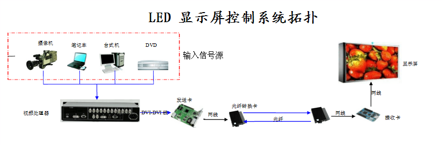
The working principle of the system:
1, the signal source can be a video output device such as a video camera, a notebook computer, a desktop computer, and a DVD.
2, the signal is converted into a DVI signal through the video processor, and connected to the sending card through a DVI cable.
3, when the distance between the control room and the display screen is greater than 100M, use an optical fiber conversion card. Use fiber optic cable for communication.
4, each display box has 1 receiving card, and the receiving cards are connected and communicated with each other using a network cable.
5, because the display screen has a T-shaped appearance, the system transmission adopts a bottom-up communication method.
6, the display screen can play a variety of content, and the input source can be switched.
7, the real-time video signal can be played on the display screen using the camera, or it can be connected to the digital set-top box to play the TV content.
8, you can use the playback software to play the pre-processed video and picture information on the computer.
To sum up, only by understanding the control topology of the full-color led display system can the full-color led display be better used and play its role. For more information, you can continue to pay attention to this site!